JZON FABRICATIONS · ASSEMBLY GUIDE

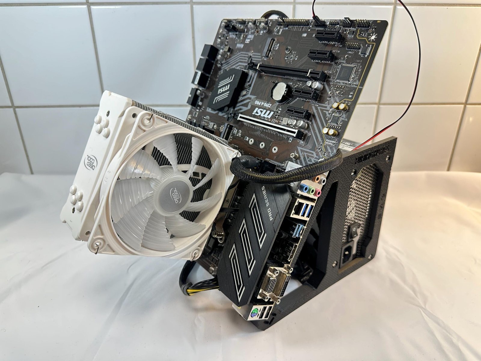
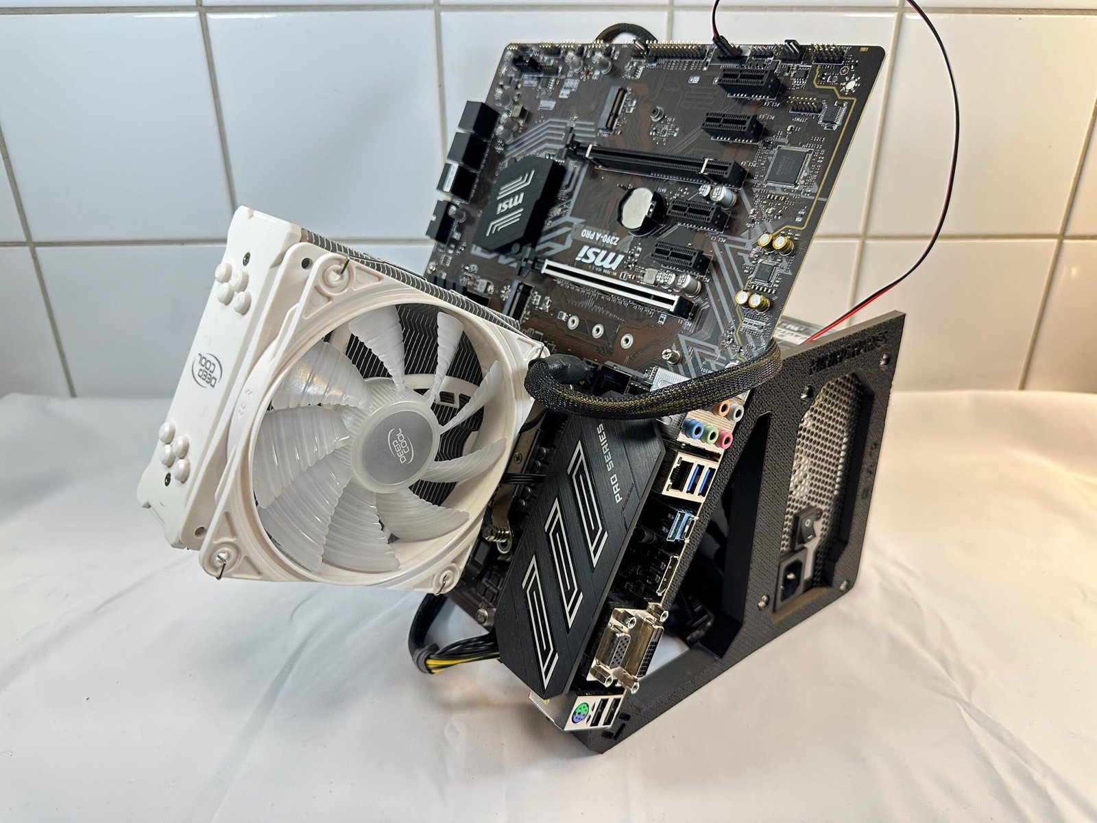
Angled Motherboard Test Bench

A clear, visual guide for assembling the frame and installing the primary PC components of the Angled Motherboard Test Bench.

INCLUDED HARDWARE

8x M3 Screws
4x 6-32 PSU screws
1x power buttons

REQUIRED TOOL

PH1 screwdriver

Use a clean, flat work surface.

TIME & DIFFICULTY

10–20 minutes

Easy

PARTS OVERVIEW

Identify the main components

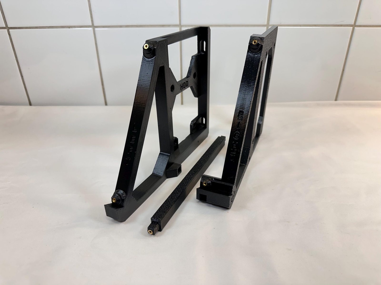
Lay out the frame sections, motherboard tray, support arms and brackets before starting.

This product is comprised of 3 main components:

  • 2x Motherboard stand legs
  • 1x Middle stabilizing bar

1

STEP 1

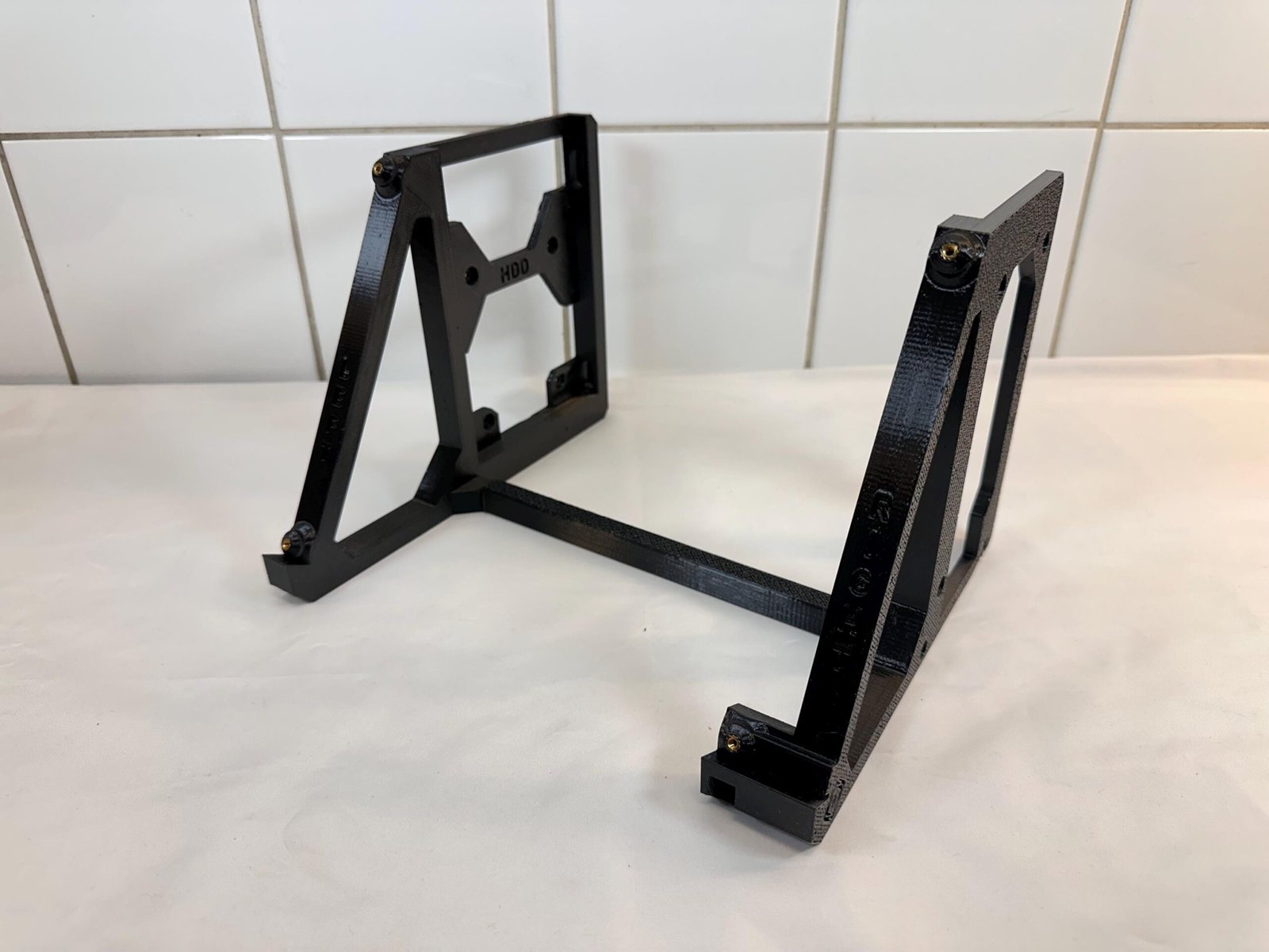
Assemble the frame

Instructions

  1. Insert the stabilizing bar between the left and right frame pieces.
  2. Secure the the bar by using a M3 screw on each side of the assembly.

Hardware used

2× M3 screws

Tip

Place the frame pieces on a flat well-lit surface for optimal assembly conditions.

2

STEP 2

Install the Power Supply

Instructions

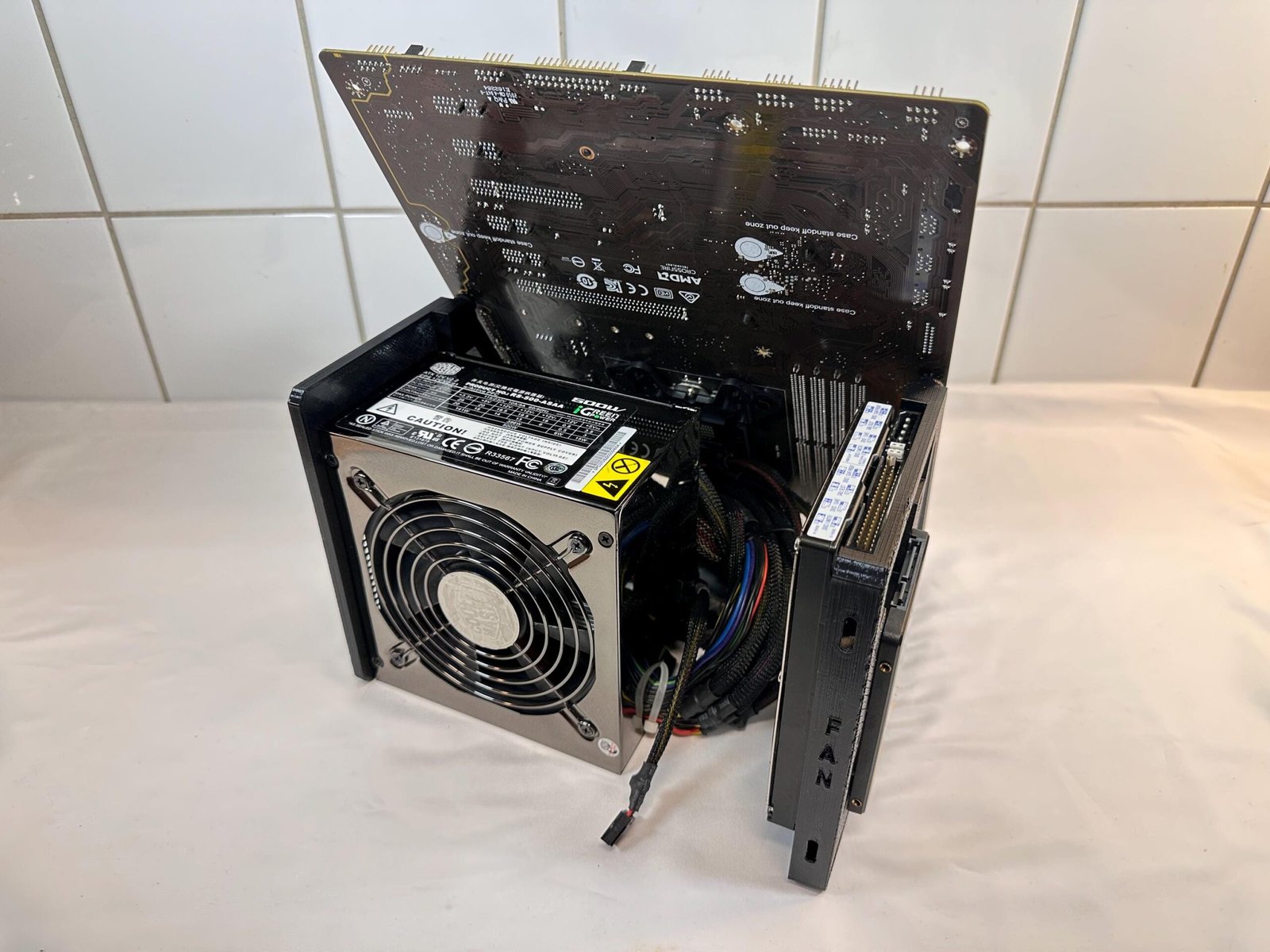
  1. Position the ATX power supply behind the PSU mounting frame marked with “PSU” with the fan facing away from the frame.
  2. Secure the PSU using four 6-32 PSU screws.

Hardware used

4× 6-32 PSU screws

Tip

Tighten the frame gradually and evenly.

3

STEP 3

Install the motherboard

Instructions

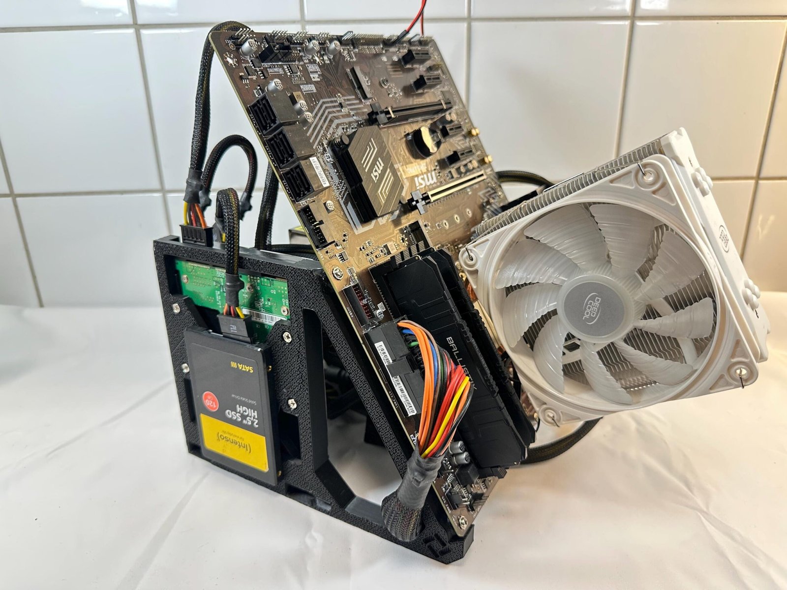
  1. Align the motherboard onto the matching standoffs.
  2. Secure the board with M3 screws without overtightening.

Hardware used

4x M3 screws

Tip

Orient the rear I/O ports on the motherboard to face them towards the PSU.

4

STEP 4

Install a fan, HDD & SSD drives

Instructions

  1. Install a 120mm or 140mm fan to the short end of the left frame, marked “Fan”.
  2. Mount either of your SSD or HDD on that particular side of said leg that is marked with the corresponding type: SSD or HDD by using 4x M3x5 screws for the SSD, or 4x 6/32 screws for the HDD.

Hardware used

4x M3 screws
4x 6/32 screws (not included)
2x Fan screws (not included)

Tip

Fan is optional. SSD has to be installed before installing the HDD. Otherwise the HDD will block the SSD’s mounting points.

5

STEP 5

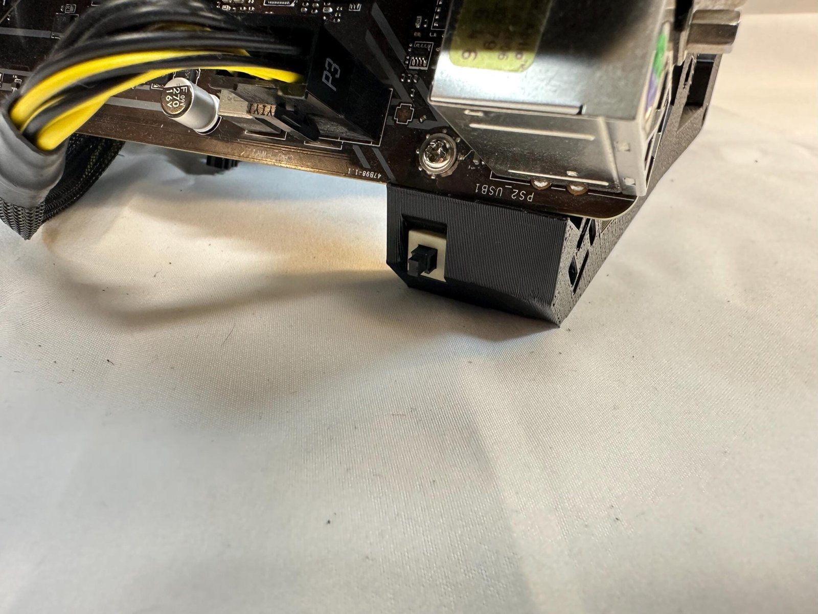
Install power button

Instructions

  1. Insert the included Power switch into the hole on the right frame.
  2. Verify that all screws are tightened properly and that cables are routed safely.

Hardware used

1× Power button

Tip

Cable management and hardware configuration may vary depending on components used.

FINAL CHECKPOINT

Inspect the complete assembly

  • All frame screws are evenly tightened.
  • PSU is securely mounted and ventilated.
  • The motherboard and storage drives are fully supported.
  • The power buttons are connected correctly.
  • No cables are touching fans or sharp edges.
SUPPORT

Need help with your assembly?

Is the instruction wrong or misleading? Perhaps you have a suggestion? We’d be delighted to hear from you regardless!

SUPPORT URL

Contact us using the form at our Contact page.

SUPPORT MAIL

Reach out to us by sending us an email.

Designed to Perform. Built to Impress.