JZON FABRICATIONS · ASSEMBLY GUIDE

Mini ITX Open Test Bench

A clear, visual guide for assembling the frame and installing the primary PC components of the Mini ITX Open Test Bench.

INCLUDED HARDWARE

20x M3 Screws
4x 6-32 PSU screws
1x power buttons

REQUIRED TOOL

PH1 screwdriver

Use a clean, flat work surface.

TIME & DIFFICULTY

10–20 minutes

Easy

PARTS OVERVIEW

Identify the main components

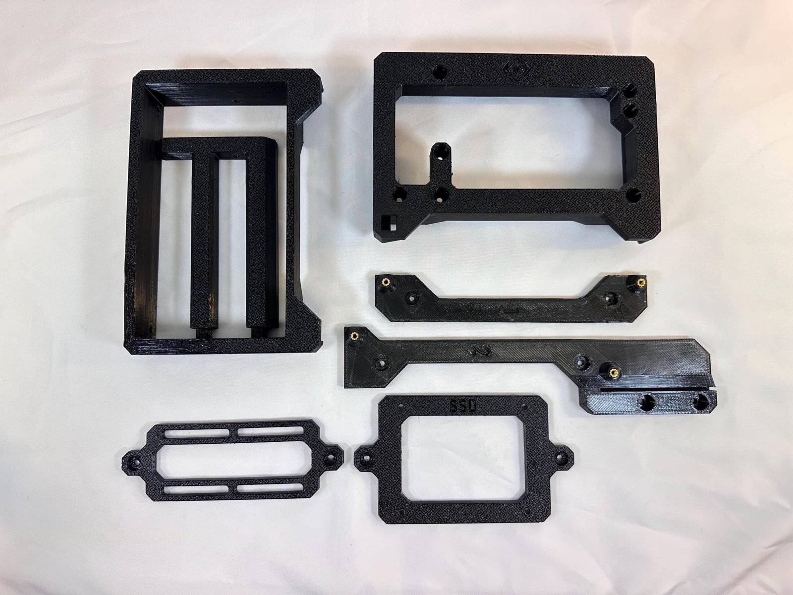
Lay out the frame sections, motherboard tray, support arms and brackets before starting.

This product is comprised of 8x main components:

  • 2x PSU mount parts – back & front
  • 2x Side panels – SSD & cable management
  • 3x Motherboard mount – With & without GPU support
  • 1x GPU bracket

1

STEP 1

Install the Power Supply

Instructions

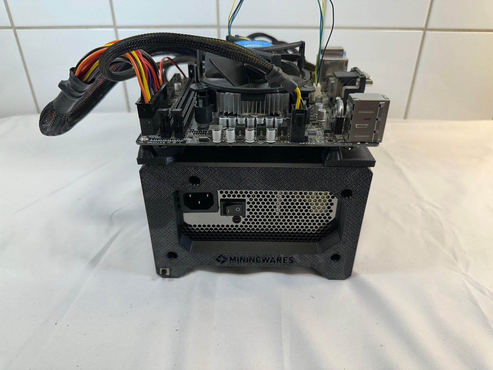
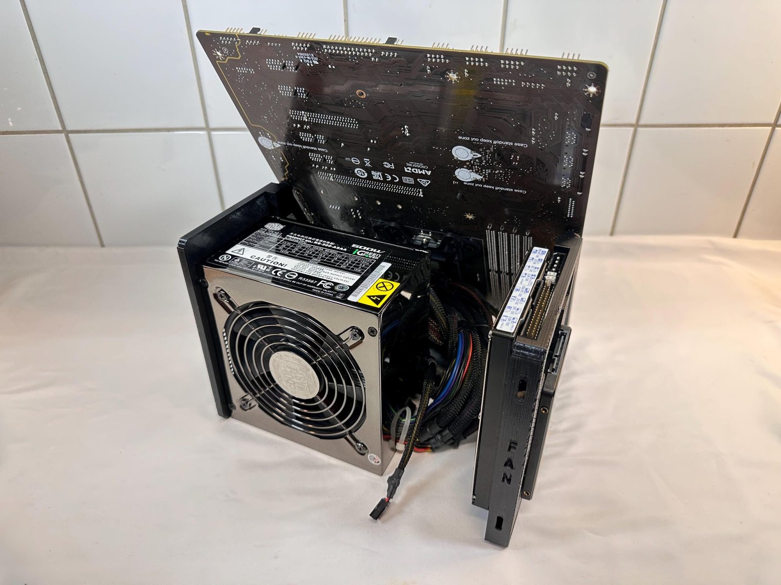
  1. Insert and securing the PSU to the front panel dedicated to the PSU using 6-32 screws.
  2. Then insert the rear panel on the PSU.

Hardware used

4× 6-32 PSU screws

Tip

Route the PSU cables upward toward the motherboard area.

2

STEP 2

Install motherboard rails

Instructions

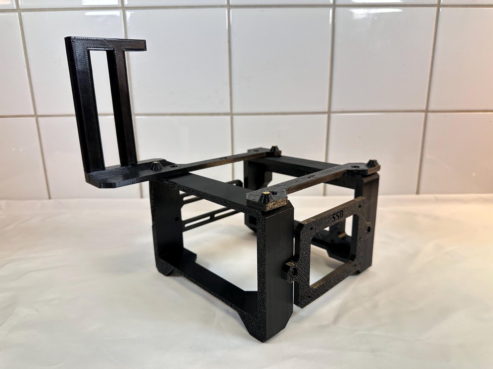
  1. Place the top motherboard rails upon the assembly and secure them to each corresponding number, as seen upon the front & rear panels, with the M3 screws.
  2. (Skip this step if you don’t plan on using a GPU)
    Attach the vertical GPU support bracket to the top motherboard rail using M3 screws, secured from the bottom.
    Ensure the bracket is fully aligned before tightening. 

Hardware used

4-6× M3 screws

Tip

  • Both motherboard rails and the PSU panels are marked with ‘1’ & ‘2’ to identify the motherboard rails’ placement.

  • Orient the rails to face outward.

3

STEP 3

Install the motherboard

Instructions

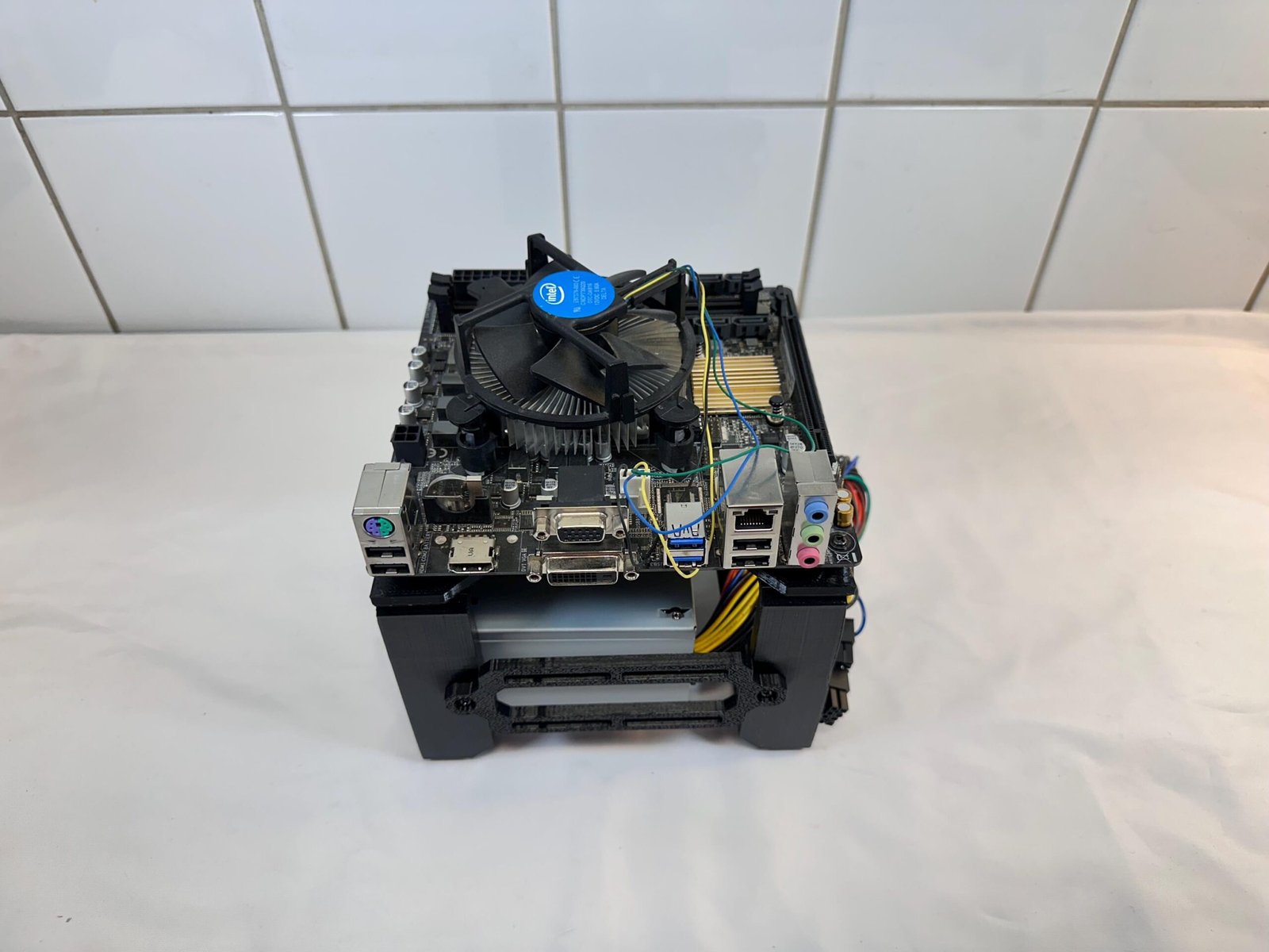
  1. Align the motherboard onto the matching standoffs.
  2. Secure the board with M3 screws without overtightening.

Hardware used

4x M3 screws

Tip

Orient the rear I/O ports on the motherboard to face them towards the PSU.

4

STEP 4

Install side panels & SSD drive

Instructions

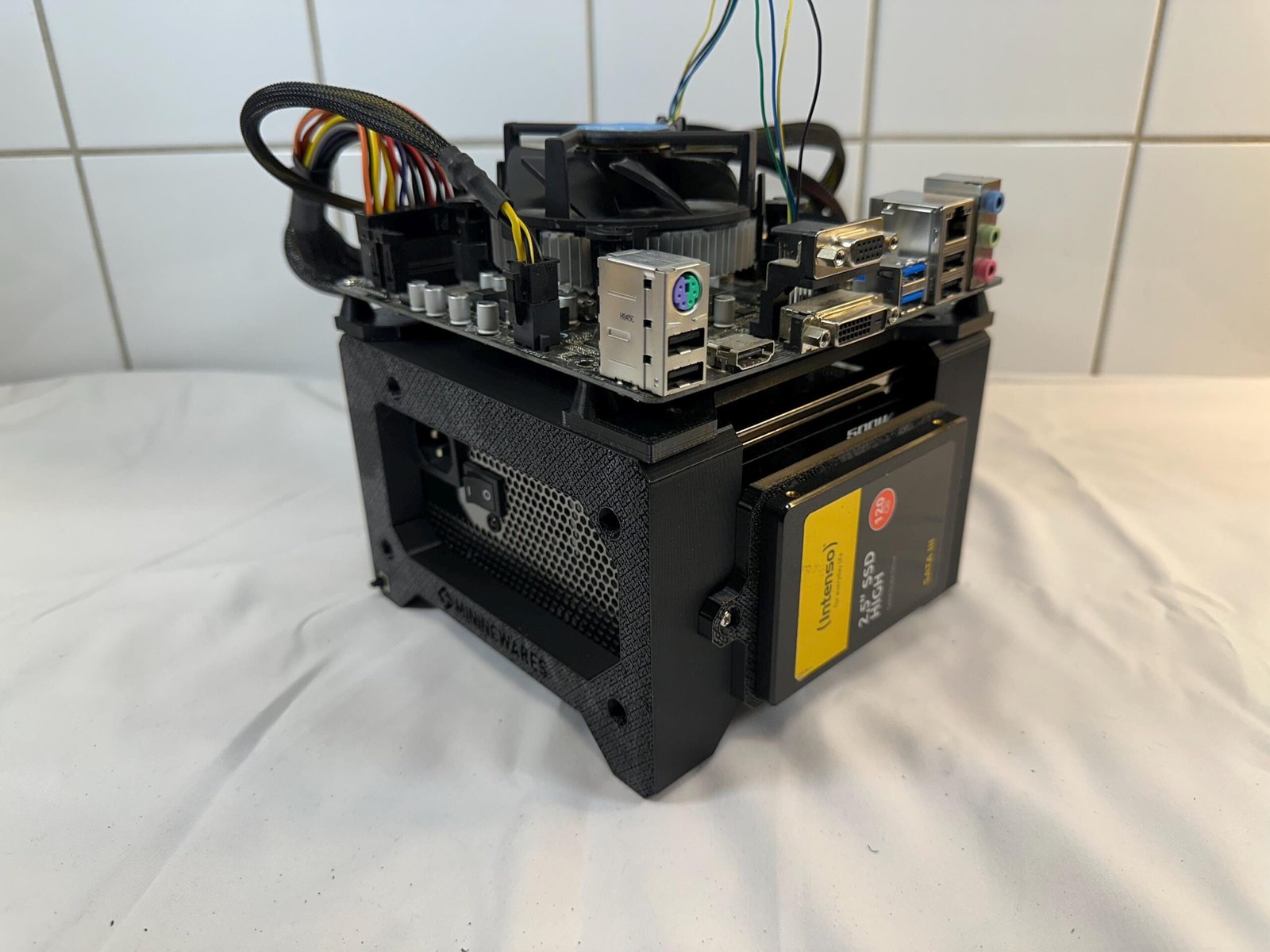
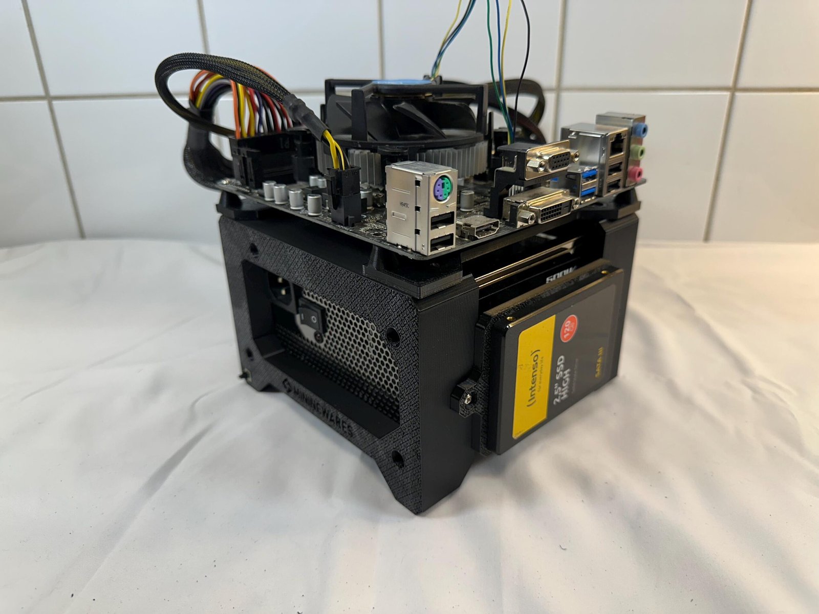
  1. Mount your 2.5” SSD to front of the SSD bracket using M3 screws before securing it to the assembly.
  2. The SSD bracket and the cable management panel are then secured to the each side of  the frame using M3 screws. 

Hardware used

8x M3 screws

Tip

The SSD is placed on top of the “SSD” marking, then mounted from the backside of the SSD-panel.

5

STEP 5

Install power button

Instructions

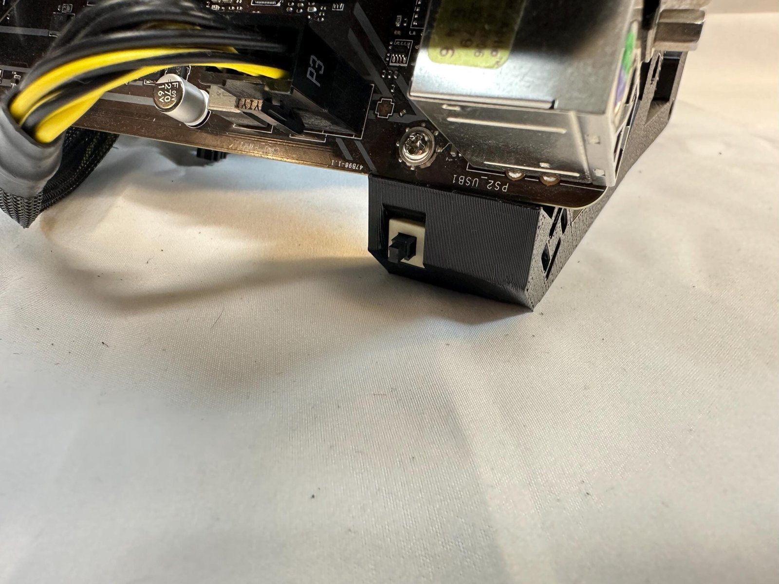
  1. Insert the included Power switch into the hole down to the bottom left of the front PSU panel.
  2. Route the Power switch connector and insert it into the motherboard.

Hardware used

1× Power button

Tip

Cable management and hardware configuration may vary depending on components used.

FINAL CHECKPOINT

Inspect the complete assembly

  • All frame screws are evenly tightened.
  • PSU is securely mounted and ventilated.
  • The motherboard and GPU are fully supported.
  • The power buttons are connected correctly.
  • No cables are touching fans or sharp edges.
SUPPORT

Need help with your assembly?

Is the instruction wrong or misleading? Perhaps you have a suggestion? We’d be delighted to hear from you regardless!

SUPPORT URL

Contact us using the form at our Contact page.

SUPPORT MAIL

Reach out to us by sending us an email.

Designed to Perform. Built to Impress.